2G HTS Wire Specification
Basic information about our REBCO 2G HTS wires is given below.
Basic Specification
|
REBCO formula |
AP or HM |
|
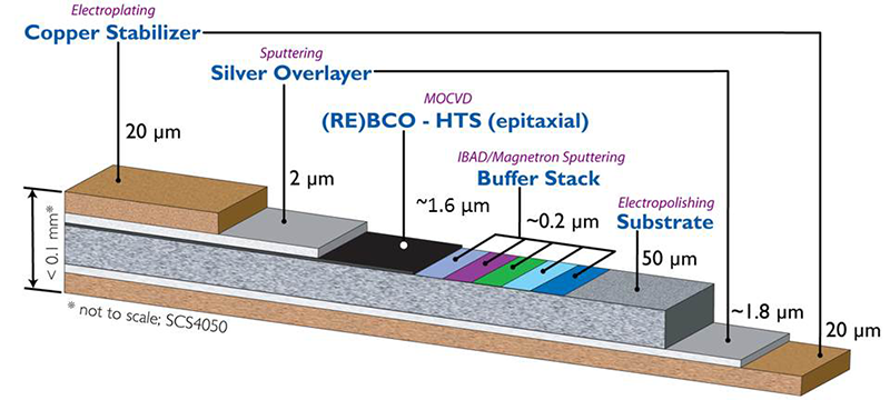
Substrate thickness |
50 µm, or 30 µm |
|
Width |
12, 6, 4, 3, or 2 mm |
|
Piece length |
200 m to 500 m (up to more than 900 m), depending on spec |
|
Stabilizer |
Ag only – Type SF (Stabilizer Free), or Ag plus electroplated Cu – Type SCS (Surround Cu Stabilizer) |
|
Electroplated Cu stabilizer thickness |
10 µm to 110 µm total (5 µm to 55 µm per side) |
|
Critical current (essentially proportional to the width, determined using 1 µV/cm criterion via transport measurement) |
|
|
Ic (77K, self-field) |
120~160 A/4mm for AP tapes, 80~120 A/4mm for HM tapes |
|
In-field critical current at various temperatures |
See graphs below for reference |
Mechanical properties
|
Axial tensile strength (at 77K, self-field, for 95% original Ic retention) |
Depending on substrate thickness and Cu stabilizer thickness (e.g., 550 MPa for tapes on 50 µm thick substrate with total 40 µm Cu stabilizer) |
|
Minimum bending diameter (at 77K, self-field, for 95% original Ic retention) |
11 mm for tapes on 50 µm thick substrate 6 mm for tapes on 30 µm thick substrate |
Other options
|
Joint |
Soldered lap joint, for Type SCS wires (joint resistivity ~ 50 nΩ-cm2 at 77K, for HTS facing HTS) |
|
Insulation |
Wrapped 25 µm thick polyimide tape (butt wrapping or 30% overlapping) |
|
Electroplated solder coating |
SnPb solder 5 µm to 10 µm per side on Type SCS tapes |
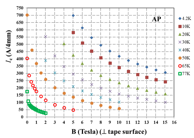
Fig. 1. Magnetic field dependence of critical current of a 4mm wide AP tape at various temperatures with the field in the direction perpendicular to the tape surface.
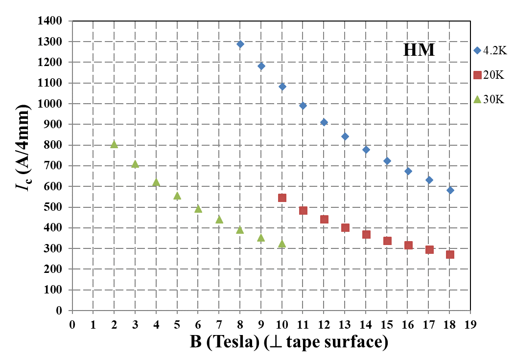
Fig. 2. Magnetic field dependence of critical current of a 4mm wide HM tape at various temperatures with the field in the direction perpendicular to the tape surface.